Stryker maintainer, this article covers the following aspects of the height management system (HMS):
- Calibration
- Driving at correct height
- Operation
- Identification of faults
- HMS IBIT
- Event list
- Common HMS Issues
- W74/W75 Replacement
- Drain the Hull
- Air Transport Box
NOTE: To view any image more clearly, right click on it and select: open link/image in a new tab.
Proper Calibration
The most important thing you can do to maintain a high level of readiness is to properly calibrate the HMS.
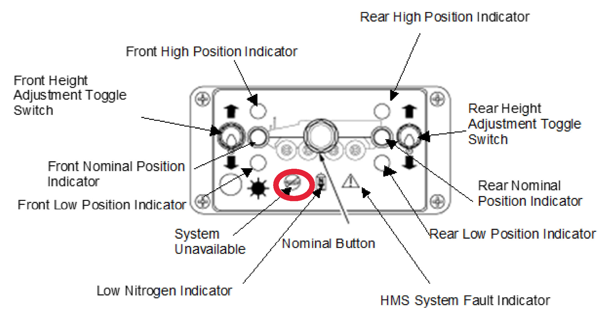
Proper calibration requires use of the height management unit (HMU), which consists of a level button, height adjustment toggle switches, height adjustment activity LEDs and status indicators.
Height management unit (HMU)
1. Be sure to use the calibration tool (shorting plug), NSN 5935-20-001-3861. The charge fittings on the quadrants (nitrogen manifold) to the hydropneumatic struts should be
open.
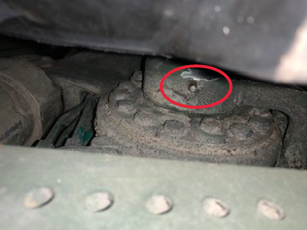
 Nitrogen critical to keeping HMS working
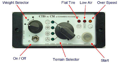
2. Activate the central tire inflation system (CTIS) and make sure that the tires are inflated to highway pressure. For more info, see TM 9-2355-311-13&P (Sep 16), TM 9-2350-450-23&P (Aug 21), TM 9-2355-363-23&P (May 21) and TM 9-2355-326-23&P (Jun 21).
 Activate CTIS
3. Place the calibration tool into the J2 port on the air transport box located in the front access cover by the drivers hatch. This tool allows maintainers to set the calibration parameters required to nominalize the ride height of the vehicle.
 Install calibration tool on J2 port
4. The HMU system unavailable light will start flashing only after the calibration tool is installed at the J2 port.
 System unavailable light will flash
5. Push the two (2) toggle switches on the HMU up and hold it for two (2) seconds, allowing the vehicle to raise to the maximum height. The low nitrogen light and the system fault icons will flash on the HMU. Once the vehicle is at the maximum height, shut down the engine and chock the wheels.
6. Measure the first and third axle struts between the collar and dust shield to make sure that the 1st axle struts measure greater than 22 inches and the 3rd axle strut is greater than 21 inches. Then have the operator start the engine, remove the wheel chocks and then depress the center button on the HMU, registering the max height.
 Measure first and third axle struts
7. Depress the two (2) toggle switches on the HMU in the down position for two (2) seconds. The front and rear lower LEDs will flash.
 Depress two toggle switches
8. Ensure that the low nitrogen and system fault lights go out.
9. Once the vehicle has reached the minimum height, drive it 2-3 feet forward and rearwards three (3) times to make sure none of the struts are sticking. Then shut down the engine and chock the wheels.
10. Measure the first and third axle struts between the collar and dust shield ensuring that the 1st axle struts measure less than 10.75-11 inches and the 3rd axle strut is less than 12-12.3 inches.
11. Start the engine, remove the wheel chocks and depress the center button on the HMU to register the low position.
- Toggle the two (2) switches up for two (2) seconds.
- Remove the calibration tool from the air transport box J2 connector.
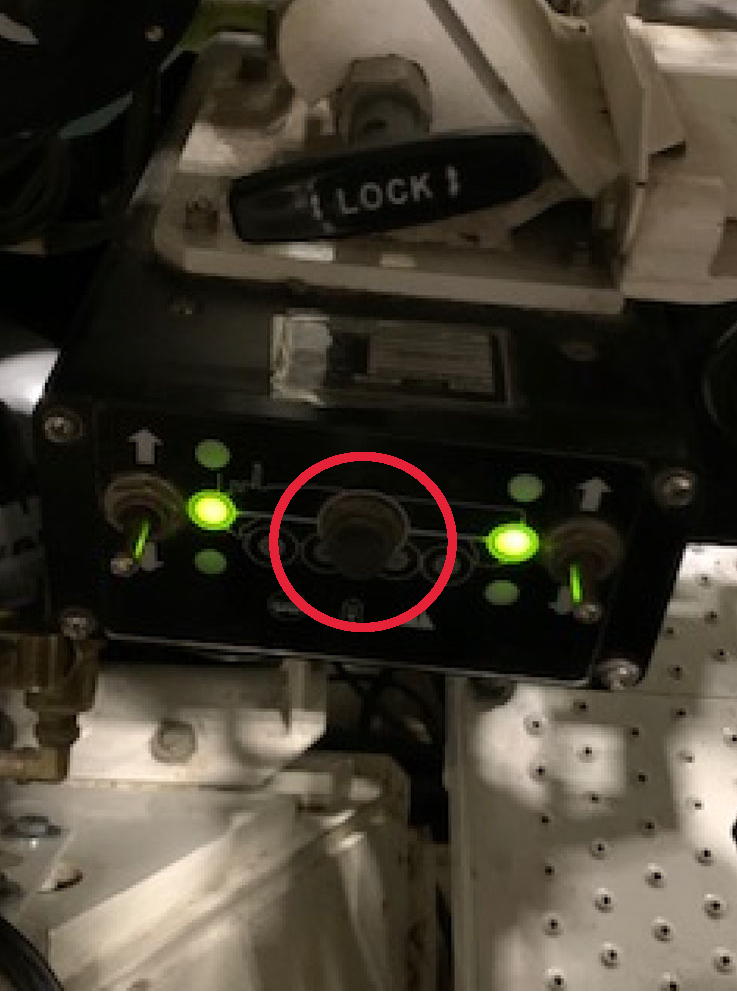
- Depress the center button on the HMU to level the vehicle.
 Depress center button on HMU
12. Once the vehicle has reached its nominal ride height, shut down the engine and chock the wheels.
13. Measure the 1st and 3rd axle struts to ensure that the 1st measures 16.4-17.6 inches and the 3rd measures 16.25-17.4 inches. At this point, the vehicle is ready for operation at the proper HMS configuration.
Driving at Correct Height
The HMS is capable of operating in the following modes:
- Normal: Suspension height of 49-51 inches at the lower edge of the sponson.
- Mine High: This position is used in high-risk areas, as well as for increased ground clearance and enhanced self-recovery.
Operation
When a level operation is initiated by the driver, the HMU interconnects the nitrogen paths between the two rear quadrants. This allows the nitrogen pressure in the rear quadrants to equalize and create one virtual rear “half.”
The HMU then compares the average height of the rear of the vehicle with the two front quadrants. If there is a height differential, the HMU continues the leveling procedure.
The HMU repeats the adjustment procedure until no further adjustments are required. The HMU will "time out" if the procedure isn’t completed within four (4) minutes.
Identifying Faults
Maintainers can identify faults with the height management system by using the video display terminal (VDT)/video display electronic terminal (VEDET). Here’s some info that
will come in handy for maintainers:
- The BIT/built in test equipment (BITE) system detects and reports faults in various devices of the Stryker platform.
- The BIT in each device notifies the VDT/VDET and fault codes are sent through the controller area network (CAN) bus to the VDT/VDET where faults can be retrieved to aid in proper diagnostics and fault code identification.
- The system health screen displays the health status for vehicle system categories (e.g., Mobility, Weapon, C4I, NBC/Climate, Height Management System and Diagnostic)
Each vehicle system category has a rolled up sub-system screen that allows operators and maintainers to view specific system component failures related to that system.
- Fault Critical Colors:
- Red: Fail Status Key
- Yellow: Degraded Status Key
- White: Waiting Status Key
- Green: Pass Status Key
- Initiated BIT (IBIT): A more thorough check of the line replaceable unit (LRU) that is selected in the System Health status screen of the VDT/VDET.
Height Management System IBIT
Follow the prompts on the VDT/VDET to run Height Management IBIT:
- Select “System Health”
- Select “Height Management”
- Select “IBIT”
Event List
The event list contains fault details for all subsystems and displays fault details, such as fault codes and possible corrections.
- Select “Active Fault” and click on “Full Details” to display diagnostic details:
- Fault code
- Type of fault
- Effect of fault
- Course of action (COA)
- Potential sources of fault (Note: Do not use this for part swapping. Instead, use it for preliminary checks and diagnostic
checks of the system.)
- Listed CAGE code & part number (Note: Before ordering parts, verify part numbers and NSNs in the RPSTL section of the Stryker parts TM.)
- Time of recorded fault
- Number of fault occurrences
- Status of fault
Common HMS Issues
It’s important for maintainers to ensure all quadrants and struts are open. If struts and quadrants are isolated, nitrogen will not flow properly, causing internal damage to the struts.
- Note: When any kind of maintenance is performed on the HMS manifold, check that all wires leaving the manifold are connected properly to the W71 wiring harness. Also, check that the cannon plugs to the harness tree are all tight. Check for plugs that are backed out, too. If you can see red on the plug, it’s loose. The wires all have the same cannon plug and are easy to mix up.
Correctly connect the gas and oil sensor. If you don’t:
- The transfer pump will not operate.
- Struts solenoids won’t open to allow nitrogen to flow.
- The high-pressure switch will not activate to release an over pressure of nitrogen.
- The HMS will not go up or down.
- The HMS will not properly calibrate.
Make sure the sensor gas (SG) and sensor oil (SO) sensors are connected correctly. Remember that the SG is on the gunner side and the SO is on the operator side.
- The low-pressure sensor (LPS), high-pressure sensor (HPS) and relief pressure sensor (RPS) all have the same type of fittings, so don’t mix them up when connecting them to their ports.
- Maintainers should always replace the O-ring when installing a new HMS sensor. If not, the sensor can be damaged and fail. Also, the HMS sensors need to be lubricated when being installed.
- Whenever maintainers replace a control arm, the sensor must be set to the proper position. A thrust adjustment is also required. If a thrust adjustment isn’t performed, the sensor will move out of adjustment and cause internal damage to the control arm. Refer to TM 9-2355-311-13&P (Sep 16), TM 9-2350-450-23&P (Aug 21), TM 9-2355-363-23&P (May 21) and TM 9-2355-326-23&P (Jun 21).
W74/W75 Replacement
If the W74/W75 isn’t installed correctly and tightly, water damage and corrosion will result, causing the control arm sensor to fail. The rear sensor can also fail.
Drain the Hull
Failure to drain the hull can cause damage to all harnesses, manifolds, sensors and solenoids.
The relief valve between the pressure tanks can also clog if the hull isn’t drained.
In cold weather the nitrogen valve can stick open and cause nitrogen to leak from the system. Keeping the hull free of fluid can help prevent this.
Here’s a previous
PS Magazine article on draining the hull:
Rear HMS Sensors
The biggest problem with the rear HMS sensors is that when they are replaced, the O-ring that goes on them is often not installed. If this O-ring is not installed, internal damage will occur causing the sensor to fail.
Ensure rear HMS sensors are lubricated. Failure to lubricate the sensors causes them to seize and not correctly operate.
 Lubricate rear HMS sensors
Air Transport Box
Whenever maintainers use the air transport box, they often forget to install the dust cover. If the dust cover isn’t installed, water gets into the box and causes the transport box to short out, making the HMS system stuck at the height that it is currently.
In summary, proper calibration, operation and attention to detail when maintaining all other aspects of the HMS is essential for proper functioning of the HMS. You can't properly calibrate without using the calibration tool. Don't use a jumper wire! It will cause internal damage to the HMU. When in doubt, follow the TM or contact your local TACOM logistics assistance representative (LAR) for help.