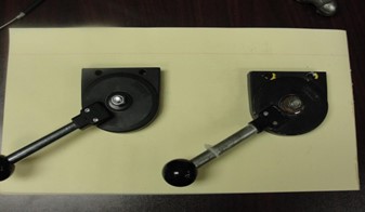
Mechanics, if you received a new throttle lever, NSN 3040-12-371-3949, from supply, then it needs to be modified prior to use. The throttle lever assembly orientation is incorrect, so the lever assembly
must be disassembled to make the necessary modifications.
In the image below, you can see a new lever assembly on the left compared with a used—but correctly oriented—lever assembly on the right. Both levers are positioned with the idle detent engaged.
New and old throttle lever assembly
Here are the instructions to complete the modification:
1. The lever assembly must be disassembled to perform the necessary modifications. If installed, you must first remove the throttle cable by loosening the two set screws near the base of the lever. Then disassemble the lever assembly by removing the self-locking nut on the center pivot bolt. The assembly can be separated as shown in the photo below.
 Throttle lever assembly disassembled
2. The orientation of the detent disk is now visible. The detent disk is the bare metal disk with an oval-shaped hole near its outer edge. To correct the new assembly, remove the detent disk, turn the detent disk upside down, and place it back in the throttle lever assembly body. Orient it so that it matches the disk’s orientation in the old assembly.
3. This step involves the installation of a roll pin to limit over-travel in the full throttle position. The pin eliminates excessive slack in the throttle cable. In the photo below, note the position of the roll pin (gray protrusion just left of the large pivot-hole in the center of the lever). If the pin is in good condition and can be removed without damage, it can be reused in the new lever. However, we have found few to be reusable. A better alternative is a new 1/8” X ½” standard roll pin.
Old roll pin position
To install the roll pin, locate the correct hole in the new lever based on the location of the pin in the old lever. Enlarge the hole with a 1/8” bit, to the original depth. While using a medium-weight hammer, install the new pin while supporting the lever.
4. Once the new roll pin is installed, use a straight edge to make sure it does not protrude above the outer edge of the lever. If it does, shorten the pin with a file, die grinder, etc. until flush with the outer edge of the lever or slightly below. The photo below shows a newly installed roll pin after shortening.
New roll pin position: below the outer edge of the lever
That concludes the modifications. Below is a photo of the new and old lever assemblies after modification of the new assembly, but prior to re-assembling the two.
Throttle assembly ready to reassemble
The next image shows the two throttle assemblies after final assembly. Both are positioned with the idle detent engaged.

Throttle assembly after modification
NOTE: If the lever assembly is to be installed immediately, be sure to install the cable stop and throttle cable, with the set screws lightly tightened, prior to re-assembly. It can then be adjusted after installation to minimize cable slack in the idle position.
All applicable changes will be reflected in the next scheduled update to TM 3-4230-238-23&P (Nov 09). For now, keep this information handy until the changes are added.